I don't have and have never really had the desire for a signal generator, but have wanted to play with the AD9851 DDS chip (a digitally controllable 0-180MHz sine wave generator) for awhile and managed to win an ebay auction for a "AD9851 Module DDS Signal Generator with Circuit Diagram" for $23.50 including shipping from China to Europe, that's cheaper than digikey charge for the chip alone!

AD9851 DDS Board
The board arrived in less than a week and was marked as "valued at $3" so no customs were charged. The Circuit diagram included on the ebay auction had no resemblance to the device I got, but it seems the design is the same or similar to most of the barebone AD9851 boards on ebay - just the chip, 30MHz crystal, header pins, bypass caps, and a low pass filter.

Approximate Schematic found on ebay (D7 and GND are swapped on my board but otherwise the components and PCB traces seem to just about match).
The device has 3 7-pin headers: 2 control headers (only 1 is needed for serial control), an output header providing the raw outputs provided by the AD09851, and 4 2-pin junction connectors, used to select serial/parallel mode, externally control the output current and for the generated sine wave itself.
The AD9851 is controlled (see the datasheet) by a 40 bit control word consisting of a 32 bit 'frequency tuning word' and an 8 bit 'control' word comprising of 5 bits of phase angle (so that multiple AD9851s can be controlled from the same clock outputing the same sine wave shifted by a different amount.), a shutdown bit, and a flag indicating whether the system clock should be multiplied (allowing the device to generate a 180MHz from a 30MHz oscillator).
The frequency of the sine wave produced is:
<system clock> * <frequency tuning word> / 2^32
so the 'frequency tuning word' required to send to the device is calculated as follows:
<desired frequency> * 4294967296.0 / 180.0e6;
Because the 'frequency tuning word' is a 32 bit integer, when it is incremented by 1 the sine wave increases by .0419Hz - also the minimum frequency - when the tuning word is set to 1 a slow rising signal can be seen on a scope.
The control word can either be transferred in parallel (byte at a time) or serially. In serial mode the chip can be controlled with only 3 pins (plus VCC and GND), basically a bit from the control word is written to the DATA pin, WCLK is pulsed high until all 40 bits have been sent and then FQUD is pulsed high to transfer the 40 bits from a buffer to the control register as shown below from the datasheet:
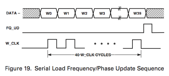
I found the reset pin could be left tied low in these simple tests but i'd do an explicit hardware reset pulse in an application. The following is some Arduino/C code to transfer the data to an AD9851 on pins DATA, WCLK, and FQUD.
1 2 3 4 5 6 7 8 9 10 11 12 13 14 15 16 17 18 19 20 21 |
#define pulseHigh(pin) {digitalWrite(pin, HIGH); digitalWrite(pin, LOW); } // transfer a byte a bit at a time LSB first to DATA void tfr_byte(byte data) { for (int i=0; i<8; i++, data>>=1) { digitalWrite(DATA, data & 0x01); pulseHigh(W_CLK); } } // frequency of signwave (datasheet page 12) will be: // <sys clock> * <frequency tuning word> / 2^32 void sendFrequency(double frequency) { int32_t freq = frequency * 4294967296.0 / 180.0e6; for (int b=0; b<4; b++, freq>>=8) { tfr_byte(freq & 0xFF); } tfr_byte(0x01); // control byte - zero phase shift pulseHigh(FQ_UD); } |
Get the full sketch here
Note that a microcontoller SPI bus can also be used to talk to the device (SPI Mode 0, LSB first, replace tfrbyte() with SPI.transfer()) with SPI SCK and MOSI pins used for WCLK and DATA pins respectively. Doing it manually allows any I/O pins to be used, but is a little slower. Full source of a SPI arduino sketch is here.
Below shows a quick oscilloscope trace for a 1303Hz wave - it looks reasonable.
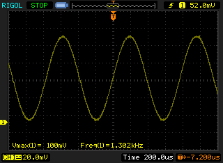
That's it for now - I might spend some more time looking at the output waveforms if I can find a use for the device.
 Subscribe to RSS
